LIGHT UP CARD INSTRUCTIONS by Nola Jacob

UPDATED: 13 September 2019 (Latest updates in red)
25th September update 1(c) TIP
NOTE: Do not cut or glue until directed.
DO NOT use metallic cardboards or papers touching the circuit as they are conductive
Using the pull/tab switch eliminates the need for foam tape.
BASIC COMPONENTS MATERIALS
1. Front of card design Card front and base as for a normal card
2. Card base Double sided tape and/or glue
3. Circuit Board Cardboard - 600gsm or 1000gsm
4. Switch Cardboard - 300 or 600gsm
5. Lights Lights, coin battery (CR2025 or CR2032)
6. Battery Use only CONDUCTIVE copper tape
- DESIGN FRONT OF CARD
(a) Choose die (or scene) featuring light/s and work out card design and placement of battery, tab and circuits.
(b) Decide finished size of card. Including borders, layers, location of embellishments as you would for normally
making a card.
(c) Decide type of lighting:
TIP: The LED pronged diode can be stuck on with copper tape or conductive glue, HOWEVER the
BEST results (brighter stronger light) will be achieved if they are soldered to the copper tape.
- Chibitronics: Easy to use, stick on (designed specifically for card making), flat (no bulk), most expensive
(about $1.60 per light). These give the best and most reliable results. Easiest for beginners. The link is for an
Australian supplier.
- Pronged diode: (link for AliExpress) Inexpensive (a few cents each from AE. Available from electronics
stores but costs more. Designed for soldering but can be adapted. Various size/colours of bulb. Adds bulk
(can cut hole so bulb is exposed and not so bulky). Note: I prefer 3mm diode for card use as the 5mm is quite
bulky.) Simply stick prongs to copper tape and cover with a second layer of copper tape... copper tape MUST
have conductive glue on back. Gently smooth copper tape with back of fingernail. Be careful not to stretch or
damage copper tape. Or use conductive glue from electronics store.
NOTE: Best results achieved if diodes are soldered to the copper tape.
- SMDs: (link for AliExpress) I found these frustrating, fiddly but fun! Requires LOTS of patience! Designed for
soldering but can be adapted for tape. Hold in SMD in place between copper tape with a teeny drop of glue or
a tiny narrow strip of double sided tape. Don't get glue on copper tape!
These should not touch the copper tape. Add conductive glue (from electronics store eg. Jaycar) on both
sides of SMD for good connection to copper tape. Don't put c/glue on top of SMD. Glue takes 24 hours to dry
and can ruin circuits if you don’t wait for it to dry. Once dry, check that lights work. Cost about 3 cents each
from AliExpress. Very bright when correctly done.
(d) Decide desired design effect. Choose suitable lights...
- is light to ‘glow’ gently through (paper) back-ground scene?
- is light to be exposed, or to shine through coloured cellophane or velum on back of light?
(e) Decide BATTERY and SWITCH positions - allow minimum 1/2” border around edge of design to stick card
together with double sided tape. Can use foam tape if design needs this. - CARD BASE
Cut card base to required size. Can be slightly bigger than front if a border is required. Score and fold. Fold can be left hand side or at top. - CUT CIRCUIT BOARD (use 600gsm or 1000gsm)
- Cut heavy duty cardboard slightly less than width/height of card. This will hide the edges of the circuit board
and ensure it is hidden behind card front.
- Cutting the circuit board slightly smaller than the card design makes it easier to be accurate with the light
positions. Or can be cut same size as front design and then trimmed if necessary.
- It is important to use a heavy cardboard so that the card does not bend and pressure is maintained over
switch and battery areas. - SWITCH, TAB & SLEEVE

A. SWITCH
- Cut 1 piece card stock 3/8” to 1/2” wide x 3” long.
- Score every 3/8” (7 score lines) and fold in zigzag pattern. Flatten as much as possible.
- Fold to form a cross shape and glue/stick together.
B. PULL TAB
- Cut (eg. 600gsm) card stock 1/2” to 5/8” wide x 3” long (or desired width).
- One end can be rounded and the word ‘PULL’ stamped near the rounded end.
C. SLEEVE GUIDE
- This holds the PULL TAB in place. If necessary, the width can be trimmed after switch is in position.
- Cut approx 1/2” wide and wrap around the PULL TAB. Make sure tab slides smoothly inside sleeve and is not
too tight. Stick/glue together.
- PREPARING DESIGN for adding lights.
- If not already done, glue background and layers in place as for a normal card.
- Glue the die cut to the card front in the final position.
- Embellishments will be added after card is completed. - MARK CIRCUIT BOARD POSITION
- Position circuit board behind card front. Temporarily hold in position with Washi tape.- Mark outline of the circuit board on card front, especially the corners. This step is helpful if you are just learning.
(Or you can cut circuit board exactly same size as card front if preferred.)
- POSITION OF LIGHTS
- With circuit board still stuck in place, turn over to front of design and carefully mark outer edge and EXACT
CENTRE of each light.
- Remove card front. We are now about to create the circuit board … - CIRCUIT BOARD
- NOW --- Carefully cut or punch through ALL the layers** to leave holes where lights will shine through. (Skip
this step if light is to diffuse through paper picture.
*SPECIAL NOTE*
Some designs will allow for background card stock layers to be cut away (circles or square-ish) to make it easier to punch through for lights on the front design.
Examples of circuits:

Circuit for Chibi Circuit for Pronged Diodes showing space for prongs
ABOVE EXAMPLE IS WRONG!! - switch is not between light and battery on one circuit. - CREATE CIRCUIT BOARD (leave 1/4" to 1/2” around edges for sticking card front to circuit board)
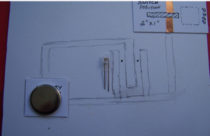
- With a pencil, lightly draw the position of the battery (3/4” x 3/4”) or trace around battery.
- Choose and mark SWITCH position (1” x 2”) on right hand side of card.
- Mark circuit positions on either side of light positions. Use straight lines with right angles
where direction changes. Minimum number of direction changes is desirable.
- One circuit MUST go from battery to light and be interrupted by the slot at the switch area
(A) CUT SWITCH SLOT
- Cut slot 1/8” wide x 7/8” long in centre of switch position. Do not cut slot closer than 1/2” from right hand side of
card to allow for tab sleeve guide to be stuck down.
- Slot will be slightly longer (1/16th to 1/8th inch) than twice width of the switch, so that copper tape is not
connecting when switched off.
(B) SWITCH
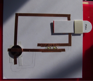
- Add copper tape (3 1/2" needed) all the way around the switch in a continuous line. This MUST match the
position of the copper circuit tape which runs through the slot.
- Smooth tape down firmly with finger to eliminate any wrinkles. Ensure EDGES of copper tape adhere properly.
- Place switch through slot.
(C) BATTERY POSITION
- Decide best battery position for the design (usually left hand side) and draw around battery (Use CR2032
or CR2025 coin batteries). Do NOT stick battery down just yet!
** OPTIONAL step ONLY if battery recess is required to reduce bulk for some designs.
- Cut a square for the battery recess to reduce bulk and make the card flatter.
- Place double sided tape (or equivalent) to cover the back of the square battery recess.
The battery will be stuck to this during making the copper tape circuits.
(D) CIRCUITS
One circuit is positive and one is negative. The two circuits must NOT touch each other.
Circuit design will depend on type of light used (eg. pronged diode vs Chibis)
- Using straight lines and fewest corners possible, stick one side of copper tape circuit in position on one side of
lights. There should be about 1/8” gap between tapes either side of the Chibi lights. Allow copper tape to extend
through centre of battery position so copper tape will be UNDER the battery making sure it matches the c/tape
on the switch.
- Stick the battery in position with double sided tape.
- Stick the second side of the circuit on other side of lights, along circuit and through the slot about 1/4” from the
right hand side of the slot and back underneath the wrong side of the circuit board. Check that SWITCH tape
aligns when switch is in right hand position.
- Stick copper tape on the other side of the slot (allow about 1/“ to 3/4” tape on wrong side)
and continue tape to battery, sticking this circuit on the TOP of the battery.
- Gently smooth copper tape with finger to eliminate any wrinkles. Do NOT stretch tape as this may cause a break.
- Check that switch glides smoothly through slot.
- Adjust slot length if necessary.
TIP: Ensure you smooth down copper tape as you go. Do not overhandle tape or components.
10. COMPETE THE SWITCH
- Slide the switch to the far RIGHT position to determine width and position of sleeve guide.
- Stick tab-sleeve to circuit board. Ensure sleeve is hidden from view.
- Slide switch to far LEFT position and insert the TAB through the sleeve. The word “PULL”
should uppermost. Determine the required length of the tab beyond the side of the card.
- The tab should be long enough to comfortably grab and pull.
- Stick the tab to the switch (switch still at far left position) and cut off any excessive length.
- Check that switch slides smoothly. Should be firm in sleeve, not loose.
(E) ADDING LIGHTS
- One side of the circuit is “positive” and the other is “negative”.
- Circuits must NOT touch each other. This will short circuit the lights and they will not work.
- Lightly stick the Chibi lights in position.
If they don’t work, then reverse the positive/negative position. NOTE they will only work if the switch is making good contact so it might be necessary to apply a little bit of pressure to the switch or battery area. Stick lights properly when in correct position.
- Check that lights are working.
- It is optional to add a small extra piece of copper tape over top of Chibi lights to ensure contact is maintained.
A second layer of copper tape can be added at side of battery to reinforce the tape.
COVER LIGHTS
On back of card front design, cover the light holes with velum or cellophane if desired. This will hide the copper tape from view. Coloured cellophane/velum can create a stronger colour.
ASSEMBLE CARD (use foam tape if card design needs this)
- With circuits facing up, place double sided tape around edges of circuit board.
- Then place card front face down and place circuit board (face down) in position that was marked earlier.
- Re-stick the temporary Washi tape to keep circuit board in position.
- Turn to front of card and …
- CHECK that the lights are in the correct position.
- If correct, stick circuit board in place and remove Washi tape. If not, adjust the circuit board position and trim
slightly if necessary.
- NEXT stick the circuit board to the card base with double sided tape.
ADD EMBELISHMENTS to complete your card.
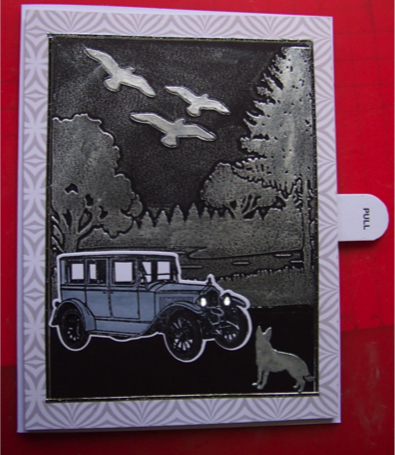
Pull tab to switch light on. Push back to switch off.
WOW! YOU HAVE NOW FINISHED YOUR LIGHT CARD! HOPE YOU ENJOYED THIS!
Copyright Nola Jacob 2019
